This post details the proper method for making automotive electrical connections using the crimp method. It is not intended to be an authoritative or comprehensive guide, but rather an introduction to basic concepts, hardware, and methods that have served me well. The intended audience is enthusiasts who don’t have any formal training in the area but like or prefer to do their own wiring projects, which can range from a simple radar detector installation through full chassis and engine harness fabrication.
Introduction
Automotive electrical problems can be amongst the most frustrating to diagnose, with loose or faulty electrical connections being a common cause. After all the time, money, and effort that goes into a race weekend, losing a race to a failed electrical connection is incredibly frustrating – and almost entirely avoidable. With a little bit of knowhow and the right tools, you can create reliable connections quickly and safely.
Several years ago I installed a fuel cell with internal electric fuel pump. I added an external connector so I could remove the cell for serviceability and soldered the wires to ensure a reliable connection – or so I thought. All was well for a few weeks, but then I started experiencing problems with the engine cutting out in a bumpy, high-speed turn at Pacific Raceways (T10). I suspected the cause was fuel delivery – which ultimately proved true – but the specific issue was time consuming and difficult to root cause.
In my effort to create a super reliable electrical using solder I ended up with the exact opposite. This sparked my interest in the correct way to make reliable electrical connections.
While testing a new fuel pump I bumped the connector and the pump sputtered. I naturally turned my attention to the connector and quickly discovered one of the soldered connections had failed. The conductor pairs were partially held in place by the connector housing and heat shrink, but it took only a little agitation to break the flow of current. The problem was easy to fix but it was a long and painful journey. In my effort to create a reliable electrical connection by soldering I ended up with the exact opposite. This sparked my interest in the correct way to make reliable electrical connections.
Why soldering is bad
Update: The topic of soldering versus crimping is often debated, and I’ve received comments to this post arguing solder as the preferred method. I’ve used both methods extensively, and maintain my opinion that crimping wins over solder, and I am in the good company of automotive, aerospace, military, and medical industries. Both methods can produce reliable connections if performed correctly, but it’s far easier, faster, and safer to produce consistently good connections via the crimp method. With the proper tools, crimping is virtually foolproof. With solder, heat is involved, proper technique requires more time and skill, toxic vapor is produced, and you’ll want to be sure to wash your hands after handling the solder.
Anyone who’s taken a metal clothes hanger and bent it back and forth multiple times knows that this is a quick and effective method for breaking off a piece of wire. In doing so, you’ve cycle fatigued the wire past its breaking point. In general, harder and more rigid materials can tolerate far fewer cycles than those which are soft and bend freely.
Your intuition should tell you that bending stranded wire will tolerate far more cycles than solid core wire. If not, give it a try using using same gauge stranded and solid core copper wire. This is why automotive wire is stranded, unlike the solid core wire used in home construction. Unlike homes, automobiles are constantly subjected to bumps and vibration, and subject to harness routing and more frequent component servicing stresses.
The issue with solder is that it can easily wick past the terminal if care is not taken. If this happens, it compromises the integrity of the connection because the solder effectively turns stranded wire into solid core wire. If after reading this post you still opt to solder your connections, ensure that the solder does not wick past the terminal pin and utilize the strain relief wings to keep the wire from flexing in the local region where solder was applied.
The challenge with solder is that it can easily wick past the terminal, effectively turning stranded wire into solid core wire.
As compared to crimping, soldering also requires more skill and time to execute properly, and adds health risks. Even for the skilled technician, time is required for heat to penetrate wire and terminals for proper solder flow, which can add days for large projects. For enthusiast automotive work, electrical work is is often performed in compromising positions with poor lighting and ventilation such as under the dashboard, underneath the car, and inside the engine bay. Such conditions imposes additional challenges to the correct application of solder, and lack the necessary ventilation to avoid breathing toxic fumes (or require the time to put such ventilation in place). And, of course, always be sure to wash your hands after handling solder!
You might be thinking modern cars utilize solder in the fabrication of their electronic components, so this is the way to go. This is for connecting discrete electrical components to a rigid plane PCB boards enclosed in an electrical housing, often with vibration isolation. If you closely inspect the terminals used to connect the wiring harness to these same components, you’ll discover that – more often than not – they’re crimped not soldered.
Why crimping is better
A properly executed crimp can be as strong as or stronger than the wire itself. It’s also very fast, safe, and easy to execute a proper crimp with the right tools with little or no skill required.
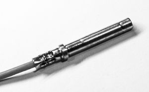
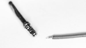
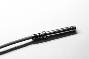
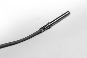
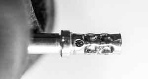
The figure below shows a wire properly crimped a solid contact pin. There wire is held pin place via 8 compression points, with 4 visible from the figure. A cross-section view is also shown in the diagram further below. The stranded wire can freely flex at the base of the connector with little or no fatigue and the wires are held in place by compressive forces that exceed the strength of the wire itself, making for a connection that is strong, durable, and virtually impervious to vibration. It took only a few seconds to form this connection with proper tooling using the foolproof procedure described by this post.

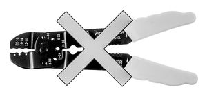
The perception that crimping is inadequate may stem from the commonplace crimper available for about $10 at your local hardware, automotive, or electronics store. This tool has no place in making automotive electrical connections and if used, adding solder probably will serve to better the connection.
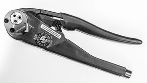
The key to a reliable crimp connection is having the right tool for the job, and knowing how to use it. The right tool depends on the type of connector being used, of which there are many. Even an aerospace quality crimp tool will not work or produce proper results if used on the wrong connector type. Some shops limit themselves to using a small handful of connector types because they don’t want to or cannot afford to purchase tooling for every type. I’m partial to Deutsch DTM style connectors for reasons stated below and which will be illustrated extensively throughout this article. For these connectors, crimp tool like the one illustrated by Figure 5 is required. If you choose a different type of connector, be sure to ask the vendor or do your research as to the proper tooling required and learn how to use it properly.
Tools and parts needed
I prefer Deutsch DTM style connectors but there are many good alternatives available, including GM Weatherpack, Metripack, and Deutsch Autosport. The methods described in this post are generally applicable to all connector styles, but you need to adjust the specific tooling requirements to match the connector type.
Deutsch DTM Connector
I prefer Deutsch DTM connectors for several reasons:
- Circular contact pins facilitate fast, foolproof crimps.
- Wedgelock insert fixes pin positions for smooth connect action.
- Covers gauge sizes (16-22 AWG) suitable for most connection needs.
- Available in 2, 3, 4, 6, 8, and 12 pin connector arrangements.
- Inline and flange mounts available.
- Parts readily available from multiple suppliers, in gold and nickel plated.
- Pins are easily removed for serviceability and housing reuse.
- All assembly components can be purchase separately, including pins.
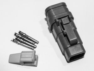

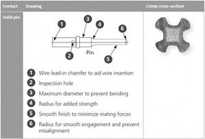
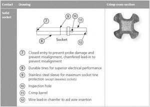
I order my connectors through Motec USA because they’ve never failed me and they also offer kits that make ordering parts a little easier (housing, pins, and wedge sold packaged together). The kits can be found in the Motec catalog available on their website. For a complete list of distributors in the USA and worldwide, visit the TE distributors webpage. I found the complete Deutsch connector catalog on the LADD Industries website. LADD is a Deutsch distributor.
In addition to complete product line, the Deutsch catalog contains lots of useful information such as produce line overview, tooling, electrical characteristics, operating condition tolerances, and how-to instructions.
You should select the housing configuration that is correct for your application. With the DTM connectors, you also have the option to select pin type. I like and use the solid pins because they’re very easy and virtually foolproof to crimp, so this is what I’ll be going into more detail on when describing the assembly process. Should you choose to also use a Deutsch connector, I recommend reading the catalog sections that describes details regarding assembly, electrical characteristics, and operating condition tolerances.
With the DTM connectors you can choose solid barrel or stamped pin types. I prefer the solid barrel pins because they result in fast and virtually foolproof crimps. This pins seen in the illustrations are the solid barrel type. Stamped pins have wings that curl onto the wire. Either pin type is fine for most applications. Just be aware there are two different types of pins, each requiring a different crimp tool. Refer to the Deutsch catalog for additional details.
Crimp tool
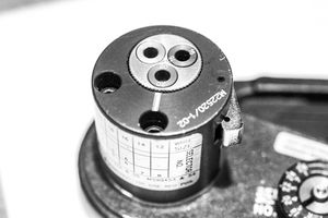
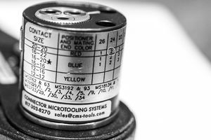
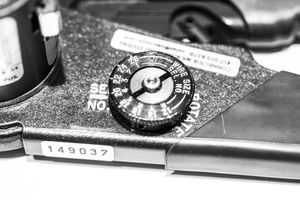
The correct tool is critical for achieving a proper crimp, else you’re probably better of soldering (as bad as that is). Check with the manufacturer or distributor for your connector of choice for information on tooling requirements. For the Deutsch DTM series connector, Tyco (manufacturer) recommends the DMC MH860 crimper, which is a circular indent style crimper conforming to MilSpec M22520. Its design accommodates a turret that can be removed and replaced by another to accommodate different contact types making it a versatile crimper.
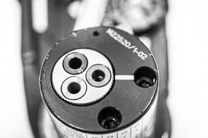
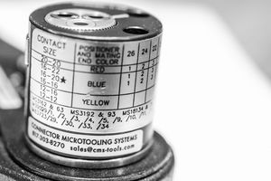
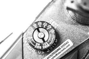
For DTM connectors, I use the M22520/1-01 “large MilSpec crimper” manufactured by Astro Tool (Figure 5), also available from Daniels Manufacturing Corporation (DMC). These cost about US$250 new. You’ll also need to purchase a crimp head (a.k.a., “turret”), which is M22520/1-02 for the large crimper and about US$80 (Figure 9). In all, expect to pay about US$330 new. These are also commonly available on eBay for about ½ the cost, which is how I purchased mine. It sounds like a lot of money for a crimper, but its foolproof design will save you tons of time and you’ll get perfect crimps every time. I’ve used a number of different contact types and associated crimpers and this is by far my favorite, so I seek out connectors incorporating a solid round pin design for all of my wiring projects where applicable.
Wire
Although not required in order to achieve a good crimp, I use Tefzel insulated wire whenever possible. It is military spec (MilSpec 22759) and used by F1 racecar and airframe constructors. Definitely overkill for stereo and radar detector installations, but if building engine or chassis harnesses, or routing wire through harsh environments (temp, oil, moisture, etc.) then I recommend you consider it if long-term, trouble free performance is desired. I indiscriminately use Tefzel wire for all of my jobs given the choice.</p>
Like a quality crimper, you’re not going to find Tefzel wire at your local hardware, electronics, or automotive store. You’ll need to order it online but there are plenty of suppliers. I get mine from Pegasus Auto Racing Supplies.
For automotive use, always use stranded wire for flexibility. Solid core wire has no business being in an automobile.
Wire stripper
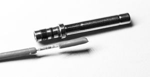
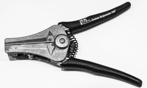
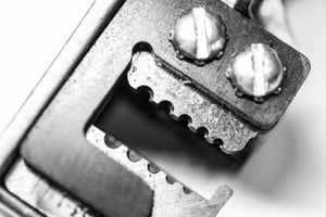
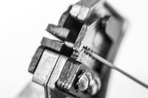
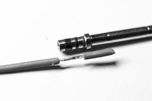
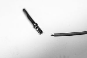
A wire stripper tool is used to strip the insulation from the endpoint of the wire being inserted into the electrical contact to be crimped. When stripping, leave the insulation being stripped from the wire covering the tip of the wire so that it can be easily removed by hand (), but so that it protects wire strands from fraying at the endpoint. This will help to ensure a smooth insertion into the connector housing. You’ll also want the strip length be correct for the contact being crimped. A quality wire strip tool will help you easily achieve these goals.
As described in the illustrations below, I use the Ideal Stripmaster wire stripper. It’s expensive but only absolutely required if using Tefzel wire, else less expensive strippers of similar design can be used with good success.
Step-by-step procedure
Finally, I’m going to describe how to execute a proper crimp using a solid round contact for a Deutsch DTM connector. Different contact types involve different tooling, but the overall process remains largely unchanged.
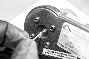
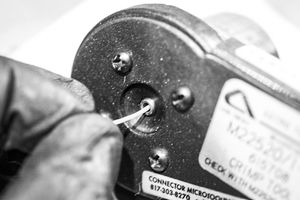
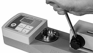
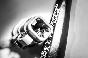
The following steps are DTM connector specific and have nothing to do with crimping. They illustrate pin insertion and connector housing assembly. I’m using different wires (Tefzel insulated) crimped from a previous job so don’t be confused about why not red 24 gauge wires like the ones crimped above.
LADD is a Deutsch distributor.

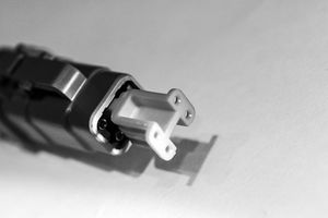
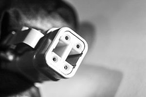
Be sure to document your pin assignments and save them someplace safe.

Wire labeling
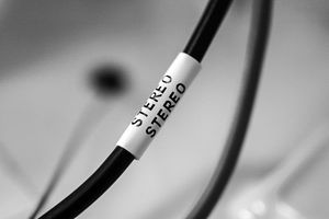
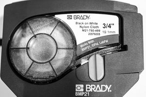
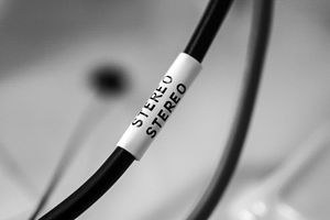
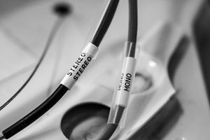
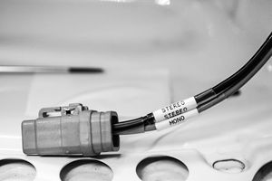
I’m also going to discuss wire labeling even though it contributes nothing to the reliability of a connection, but it goes hand-in-hand with topic and therefore worth mention.



Video demonstration
About feature image

Comments
I’d love to hear your feedback, good or bad. Please leave comments below.
Leave a Comment